
Appendix A
RADWIN Online Link Budget Calculator: Theory
Link Budget Calculator Internal Data
For each product (or Regulation and Band) the calculator stores the following data required for link budget calculations:
• Maximum Tx power (per modulation)
• Receiver Sensitivity (per modulation) for Ethernet service and for TDM services at various BER
• Maximum linear input power (used to calculate minimum distance)
• Antenna gain and cable loss for ODU with integrated antenna
• Available Channel Bandwidths

where:
Site A is the transmitting site
Site B is the receiving site
PathLoss is calculated according to the free space model,


where Sensitivity is dependent on air-rate.
MinRange is the shortest range for which  per air-rate.
MaxRange (with Adaptive checked) is the largest range for which 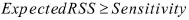 , at the highest air-rate for which this relationship is true. In a link with adaptive rate this will be the actual behavior.
MaxRange (for a given air-rate) is the largest range for which  .
.
The Ethernet and configured TDM trunks throughput is calculated according to internal product algorithms.
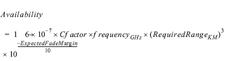
The Service Availability calculation is based on the Vigants Barnett method which predicts the downtime probability based on a climate factor (C factor).
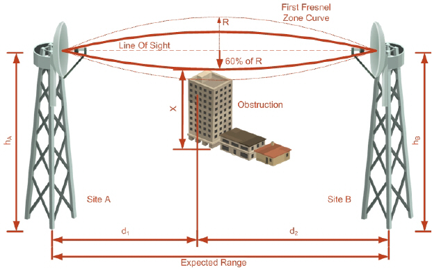
The recommended antenna height required for line of sight is calculated as the sum the Fresnel zone height and the boresight height. See About the Fresnel Zone below. Using the notation of Figure A-1 below, splitting ExpectedRange into d1 + d2, the Fresnel zone height at distance d1 from the left hand antenna, is given by
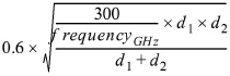
For the most conservative setting, we take the mid-point between the antennas, setting 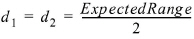
which gives 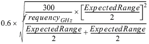
simplifying to 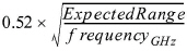 .
.
The boresight clearance height is calculated as: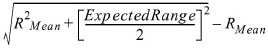
where 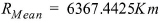 .
.
The Fresnel zone (pronounced "frA-nel", with a silent “s”) is an elliptically shaped conical zone of electromagnetic energy that propagates from the transmitting antenna to the receiving antenna. It is always widest in the middle of the path between the two antennas.
Fresnel loss is the path loss occurring from multi-path reflections from reflective surfaces such as water, and intervening obstacles such as buildings or mountain peaks within the Fresnel zone.
Radio links should be designed to accommodate obstructions and atmospheric conditions, weather conditions, large bodies of water, and other reflectors and absorbers of electromagnetic energy.
The Fresnel zone provides us with a way to calculate the amount of clearance that a wireless wave needs from an obstacle to ensure that the obstacle does not attenuate the signal.
There are infinitely many Fresnel zones located coaxially around the center of the direct wave. The outer boundary of the first Fresnel zone is defined as the combined path length of all paths, which are half wavelength (1/2 l) of the frequency transmitted longer than the direct path. If the total path distance is one wavelength (1 l) longer than the direct path, then the outer boundary is said to be two Fresnel zones. Odd number Fresnel zones reinforce the direct wave path signal; even number Fresnel zones cancel the direct wave path signal.
The amount of the Fresnel zone clearance is determined by the wavelength of the signal, the path length, and the distance to the obstacle. For reliability, point-to-point links are designed to have at least 60% of the first Fresnel zone clear to avoid significant attenuation.
The concept of the Fresnel zone is shown in Figure A-1 above. The top of the obstruction does not extend far into the Fresnel zone, leaving 60% of the Fresnel zone clear; therefore, the signal is not significantly attenuated.
For more about Fresnel zone, see http://en.wikipedia.org/wiki/Fresnel_zone.