Understanding the Link Profile
The examples in this chapter were created using the RADWIN OLBC for RADWIN 2000 products. Link Profiling is generic, applying equally to RADWIN 5000 HPMPand WinLink 1000 products.
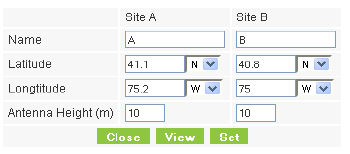
Suppose for example, you enter the following coordinates and click Set:

The range will be calculated and displayed:

|
If you click View, a new tab or window is opened by your browser with the following display:
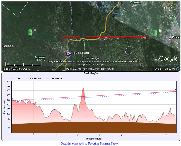
Figure 5-1: Google Earth plug-in: Terrain display and Link Profile
|
In your browser, click either of the sites - say A:
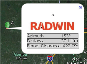
Figure 5-2: Google Earth plug-in site display
The display shows the azimuth (compass setting) to the other site (B), the distance and the Fresnel clearance (60%).
You may return to the Coordinates window and click Set to transfer the results to the distance calculation area in the RADWIN OLBC main window. The display of Figure 5-1 remains open.
|
Suppose that we enter the following coordinates (somewhere in the Sahara Desert):
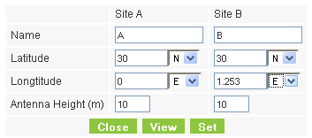
Here are the results:
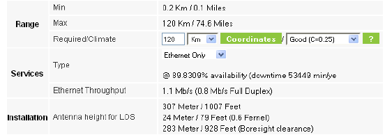
Here is the Terrain Display and Link Profile from the plug-in:
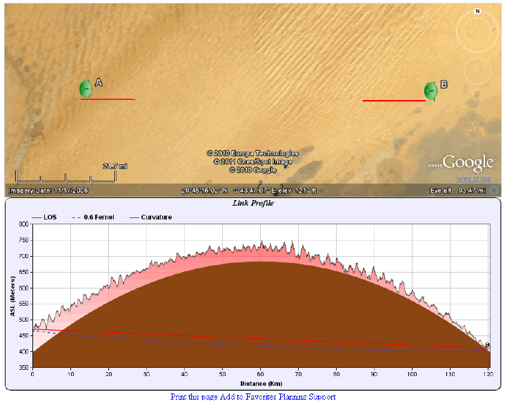
The Link Profile shows the contribution of the terrain and the earth’s curvature to link interference for the selected antenna height. The latter appears exaggerated due to the choice of vertical scale. The actual contribution of the earth’s curvature over a range of 120 km (74.6 miles) is 255 m (837’). This situation is untenable, so we need to refine the profile.
Suppose for example we had tall buildings or hills at both link sites, enabling us to set our antennas 320m above ground level:
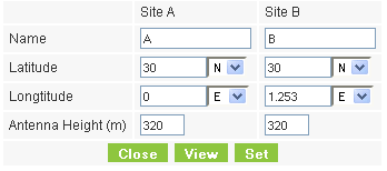
The calculation results are as before -
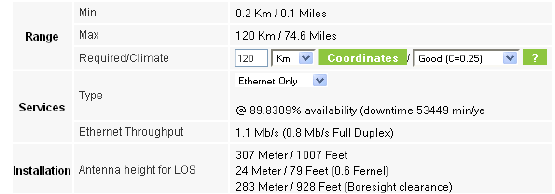
but this time the link profile is quite different:
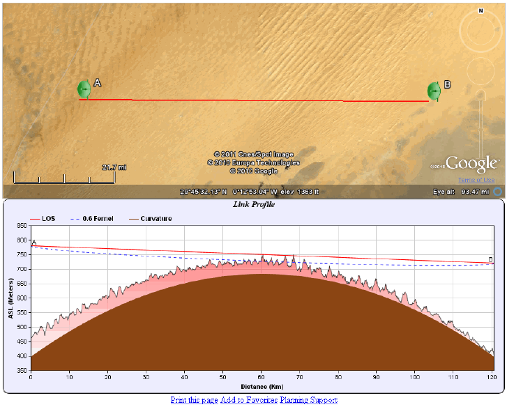
This time we have LOS, but there is some terrain intrusion into the 60% Fresnel zone. A possible solution would be to split the link into two roughly equal segments, which would also reduce our tower heights to something more realistic than 320m! This takes us into the domain of Link Planning which is beyond the scope of this Guideline. RADWIN supplies a Link Planner to meet this need.
For Further Information about Link Planning
Just below the link profile, there are three Internet links:
• Print this page
• Add to Favorites
• Planning Support
Clicking the Planning Support link opens an email page:
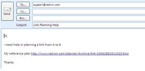
Your Terrain Display and Link Profile are saved on the RADWIN OLBC site as shown. (If you Ctrl-Click the site it will open your link site in Google Earth.)
Feel free to add further comments or questions to the email. A RADWIN Professional Support engineer will contact you by return email as soon as possible.